Intervawhat? An intervalometer is a camera controller that signals the camera to take a picture after some set interval. This is really useful for creating timelapse videos. For a long time, I used my TI-89 calculator to create timelapse videos with my Canon digital Rebel XTi. It worked quite well, and the calculator in/out port just happened to be the same as the Canon remote shutter port, so there wasn't even any hardware hacking involved. However, it was a bit buggy, as calculators are obviously not made to control cameras. There were also some limitations to using the calculator. For example, I wasn't able to easily to high dynamic range timelapses with the calculator. I also just needed a project to work on, so I started this Arduino-based camera controller.

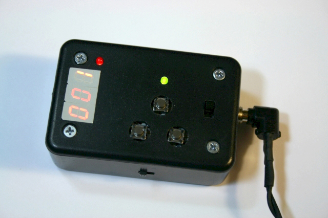
I made a prototype using an Arduino Duemilanove (with an Atmega328 chip) and a breadboard. This was mostly to test the software, but it also helped me figure out exactly what sort of hardware interface I wanted. I settled on a 3 digit display comprised of 7-segment LED displays to show the user the number of pictures taken, the time interval between pictures, and any other information. I also set up three buttons: start/stop, increase, and decrease. The increase and decrease buttons are for setting up the timelapse: changing the time interval and number of pictures to be taken. Finally, I decided to use two toggle switches in the interface. One is to switch between HDR mode and normal mode, while the other is to swith the interval units from seconds to minutes. This saves me from needing to press the "increase" button 600 times to get to an interval of 10 minutes (600 seconds). At first, I planned on using the Arduino board pictured in the prototype, but soon I realized that I wanted a small form-factor, so I bought an Arduino Pro Mini from Sparkfun to use in the intervalometer.
Here is the final circuit schematic for the intervalometer. If you're interested, you can take a look at the Arduino source code.
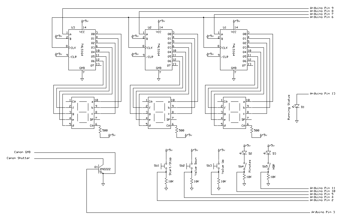
I knew I wanted the whole thing to fit inside of a 2" x 3" x 1" Radio Shack project box, so a lot of the soldering would have to be pretty tight. I started with the 3 digit display. The 7-segment LED displays are driven by three 74164 shift registers. A blog called Paul's Electronics provided a nice primer for shift registers, 7-segment displays, and controlling them with an Arduino. Essentially, the shift register allows you to control 8-bits of data using only one microcontroller output pin. The 8 bits of data are sent in to the shift register serially (i.e. one bit at a time) and then the shift register outputs the states of each of the 8 bits in parallel (i.e. all at once). After triple-checking my pinouts and wiring, I set to work soldering the displays to the shift registers on a printed circuit board. I set up the displays at 90 degrees to the shift registers so that the registers would sit in one of the pre-made board slots in the Radio Shack project box.


When the display assembly was soldered together and working, I had to start on the user interface. The first step was to cut a hole for the display, which I managed with a Dremel tool and a small file. It actually came out really nicely, and the 3 LED digits friction fit perfectly into the rectangular hole.


 and power (r) plugs")
I drilled a two holes in the side of the box: one for the output to the camera, and one for DC power in. The camera output plug is just a 2.5 mm sub-mini headphone-style jack for my Canon DSLR. This is really convenient, because it's a standard plug type, which makes it good for hacking--you can find a compatible cord in pretty much any electronics store. The Canon remote shutter control is very simple and only has 3 pins. There is a ground pin, an autofocus pin, and a shutter pin. When the shutter pin is shorted to the ground pin, the camera takes a photo. The Arduino sends a signal to a transistor which essentially connects the shutter and ground pin on the camera connector. This way, I can electronically signal a photo to be taken on my camera.
I spent a while thinking about how to mount the buttons so that the cover of the device would remain easy to remove for reprogramming or maintenance. I settled on a solution that actually uses the vertically-mounted shift register chips to support a piece of perforated circuit board. The board is supported on the opposite side using some screw holes already built into the project box and some aluminum standoffs. This makes for a very sturdy platform that's easily able to withstand someone pushing on it repeatedly, but is still able to be removed easily. The three buttons (scavenged from an old audio amplifier) sit right on top of the circuit board, and they are soldered in place on the underside. I added a switch under the buttons to toggle between interval units of seconds and minutes. I also added a small red LED near the display to notify the user when the units are set to minutes. I soldered the whole thing together with the Arduino Pro Mini, and it was nearly done!


The last few steps were to finish the cover plate and add the high dynamic range toggle switch. I decided to put the HDR switch on the side of the unit, because I felt like the top was getting too crowded with buttons, switches, and indicator LEDs. The only way I could figure out to mount this swith was with epoxy, which I did reluctantly. Epoxy makes assembly really easy, but it's pretty permanent, so bad for future work or rebuilding. I did scavenge a small connector from an old iPod battery though, so the main button board is still removable from the epoxied switch. I drilled some holes for the buttons to come through and Dremeled an opening for the toggle switch. I'd still like to laser etch the case with labels and add some covers for the three buttons with icons on them.


Here is a video demonstrating the functionality of the intervalometer. I made a mistake when narrating the video: when the display shows the number of pictures to be taken, the actual number of pictures is 10 times the displayed number, not 100 as I say in the video.
Arduino Intervalometer for Canon from Trevor Shannon on Vimeo.