Soft Electronics Tutorials
Sewing circuits isn't that tricky - anyone can do it with a basic knowledge of electronics and the right materials. I wrote a few tutorials below to help show you how!
Need materials? You can buy starter soft circuit kits in my Etsy Shop!
Tutorial Topics
Basic Electronics
- Electricity
- Current, Voltage and Resistance
- Components
- Circuits
- Current and Voltage Laws
- Simple Analysis
- Building a circuit: Tricolor LED + Photoresistors
Analog Soft Electronics
- specialized materials
- sewing with components
- coin cell battery case
- soft push-button
- single LED circuit
- parallel LED circuit
- tricolor LED with photoresistors
- multimeter basics
Digital Soft Electronics
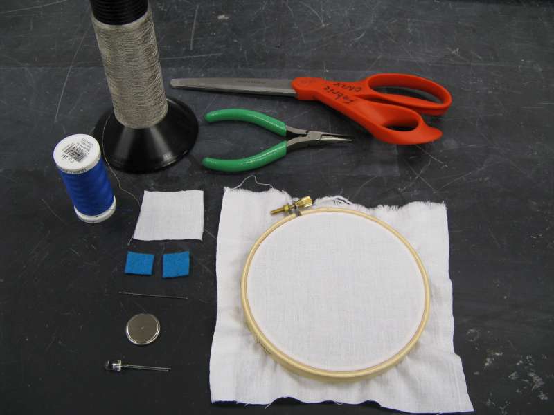
Specialized Materials
The tools and materials for creating soft circuits are pretty standard: you need your electronic components and their tools, and your soft materials and their tools. Anything that conducts electricity can be interesting here: snaps can be switches; hooks and eyes can too. There is only one special ingredient: conductive thread. This embroidery-floss-like material is the wire that makes soft circuits possible. Below is a little video on Conductive Thread if you want to learn more about it!
If you are thinking of doing digital electronics, check out the Lilypad Arduino, an open-source programmable microcontroller designed especially for sewing and use with conductive thread.
Not sure you want to invest in a whole spool of conductive thread? I sell affordable soft electronics starter kits in my etsy store!
Sewing with components
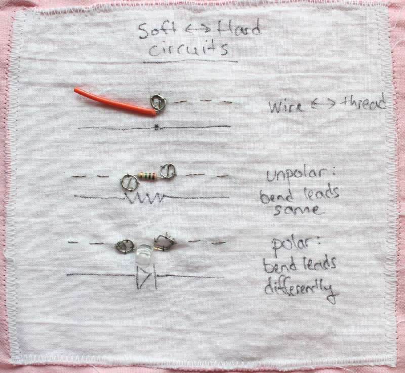
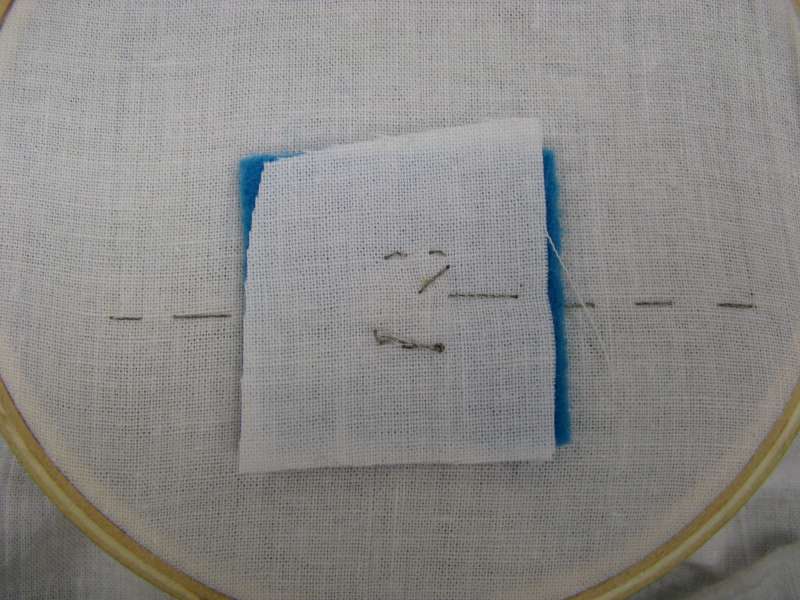
To sew traditional components one must make them into sewable buttons. Using needle-nosed players, bend the leads of the components into little sewable loops, then sew them down with at least three stitches of conductive thread.
If the component will be under physical pressure, reinforce the conductive thread stitches with normal thread, which is stronger.

Another option to connect between hard and soft elements in a circuit is to terminate the soft portion with a snap. A mate can be made by soldering a piece of wire onto the other half of the snap.
This technique can be used for switches, but also to allow a portion of the circuit to be disconnected before washing.
Use normal cotton / polyester thread to secure the snap after sewing it with conductive thread.
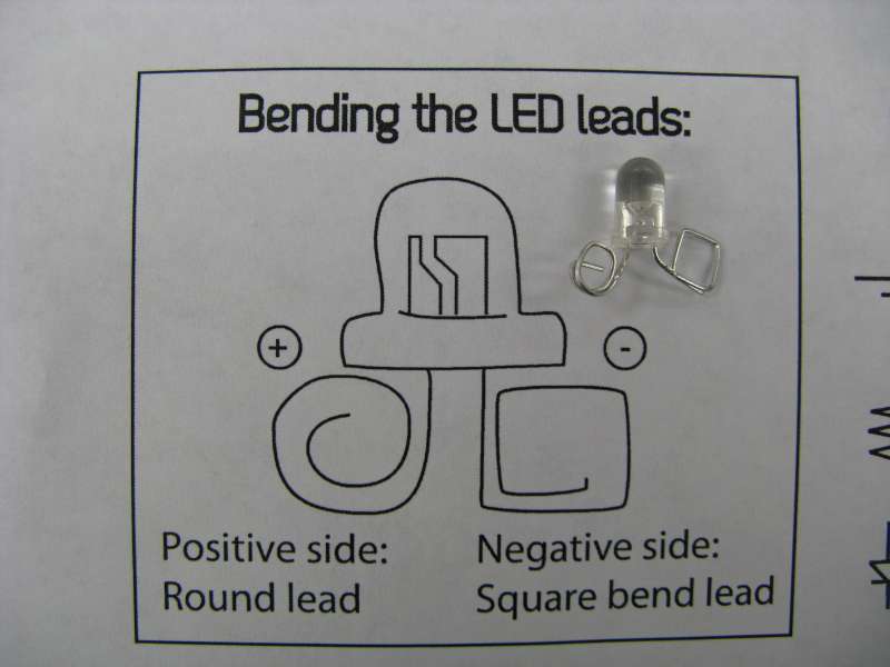
For diodes and other components with a polarity, bend the negative lead into a square, and the positive lead into a circle. This allows you to tell them apart easily after they are bent.
LEDs have a longer positive lead, and a flat bit on the plastic edge on the negative side.
(This wise idea by Becky Stern. Make your own convention and stick with it!)
Coin cell battery case
Materials: 2 squares of felt (smaller than the battery), 1 small square of fabric (larger than the battery) and the project to which the battery pack will be attached. Conductive fabric optional.
Using the conductive thread, sew one small square of felt down to your project, making lots of zig zags that are less than the width of the battery.
If you have conductive fabric, you can use a little patch of that instead of thread zig zags. Stitch conductive thread in the conductive fabric to go to the rest of the circuit.
The felt isn't strictly necessary, but it helps the electrical contact by raising the conductive material, increasing the squeeze on the battery. The point is to make a nice place for the battery to make contact.
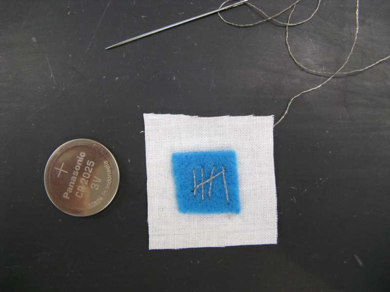
With a new trace of conductive thread (or a new piece of conductive fabric), sew the other piece of felt to the small square which will be the battery pouch in the same manner: try to make lots of space for electrical contact with your battery.
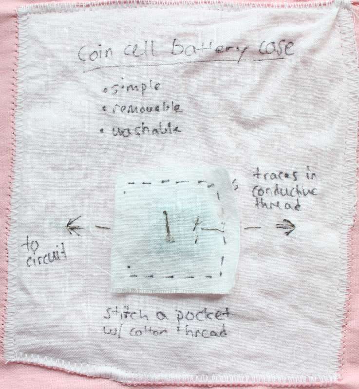
Align the two patches, and sew up 3 sides to create a pocket. This is easier on an embroidery hoop.
The tighter you sew the pocket, the better the electrical connections will be. Sometimes my battery packs act as buttons too -- you have to push them to make the electricity flow.
Soft push-button
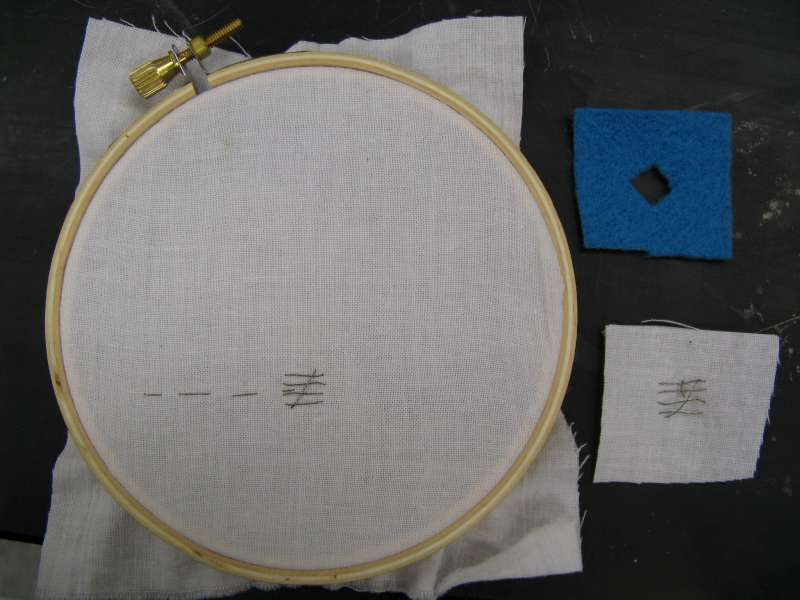
Materials: conductive thread, felt, fabric.
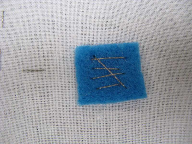
Cut a small (finger-tip-sized) hole in the center of a piece of felt.
Using conductive thread, sew a zig-zag on your bottom layer of fabric slightly larger than the hole, and another zig-zag on the top piece of fabric. Or, use traces of conductive fabric instead of zig-zags.
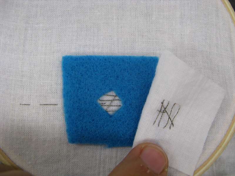 Create a sandwich of the felt doughnut between conductive thread traces. The doughnut will hold the traces apart until force is applied.
Align the traces over the doughnut hole. Sew to the rest of the circuit, being careful the two conductive thread pieces won't touch without being pushed.

Stitch around the outside of the button to hold all the pieces in place, using normal thread.
Ta da! A soft push-button which can be added to any circuit.
Use more layers of felt doughnuts for a less sensitive button.
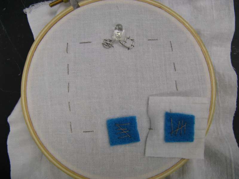
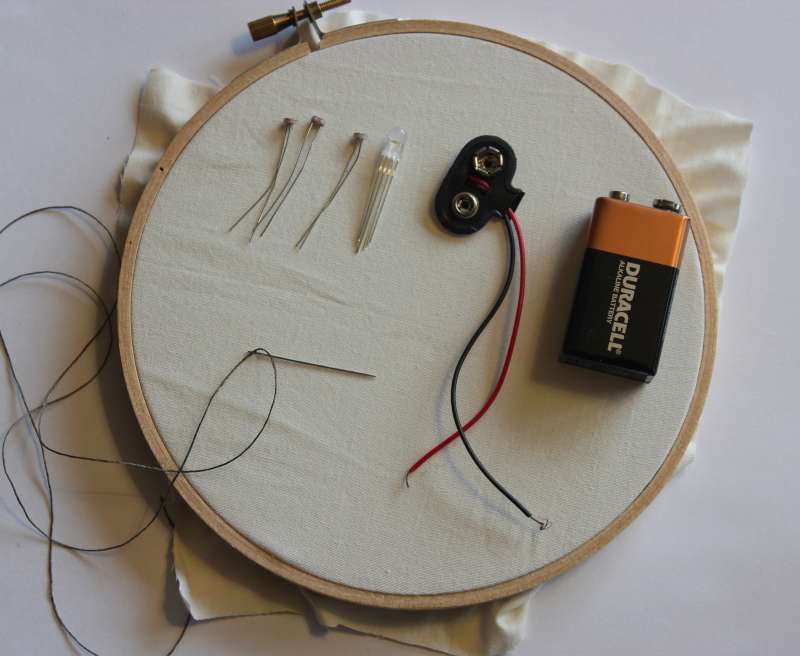
Single LED circuit
To make a soft circuit with a battery and a single LED:
Materials needed:- Scissors
- Needle-nose pliers
- Sewing needle
- Embroidery hoop
- Normal thread
- Conductive thread
- 3V coin cell battery
- 2 pieces of felt (smaller than battery)
- Fabric square for battery pouch
- Fabric to sew onto
- 1 LED with forward voltage less than 3V
- Fabric glue (optional, not shown)
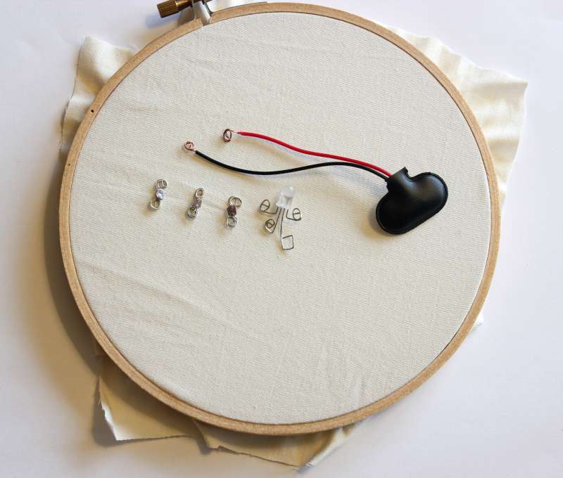
Using the pliers, bend the LED's leads into sewable loops.
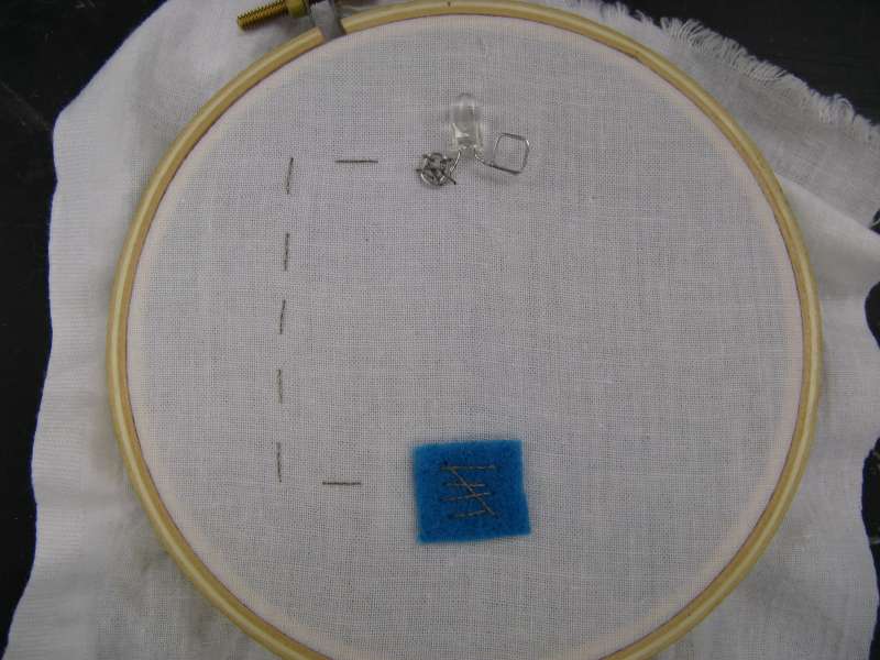
Sew one side of a coin cell battery case onto your large piece of fabric.
Then, stitch over to one side of your LED and sew it down with at least 3 stitches. Tie the end, cut the thread, and put a drop of glue on the knot to keep it secure.
Sew with conductive thread from the top of the battery pouch to the other lead of the LED, making sure not to touch your first trace (this would cause a short circuit!). Knot and cut your thread.
Note: because our 3V coin cell battery can't supply much current, we don't need to worry about burning out the LED or using a resistor here.
Before going any further, put the battery between the two pieces of felt and see if your light turns on. If it doesn't work, flip the battery around. If it still doesn't work, check you aren't short circuiting somewhere!
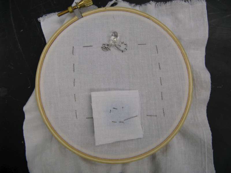
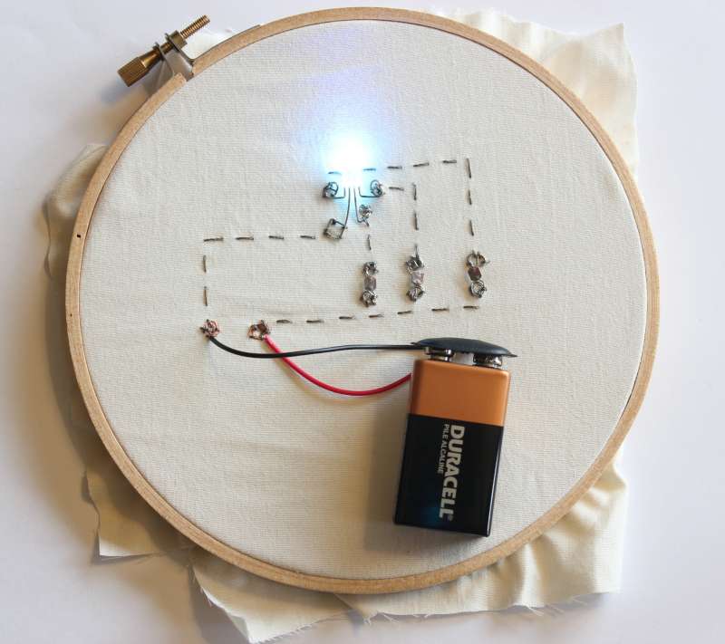
In this view, I've opened the upper flap of the battery pack. Note how the two pieces of conductive thread, one for each side of the circuit, are not touching anywhere!
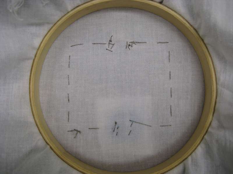
The threads behind the LED (top of hoop) do not touch. There are two separate traces here: the positive trace and the negative trace. If they accidentally touch, the LED won't turn on because current can flow directly from one side of the battery to the other, bypassing the LED.
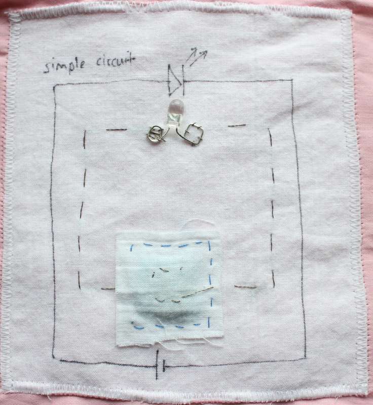
Got it to light up? Great! Now, sew around 3 sides of the battery pouch with normal thread so that you can remove and replace the coin cell battery.
In this example, the battery slips in to the pocket from the left.
Now, decorate your circuit to make it pretty! Or, try something more complex, like using several LEDs in parallel. But keep track of your positives and negatives!
Parallel LED circuit
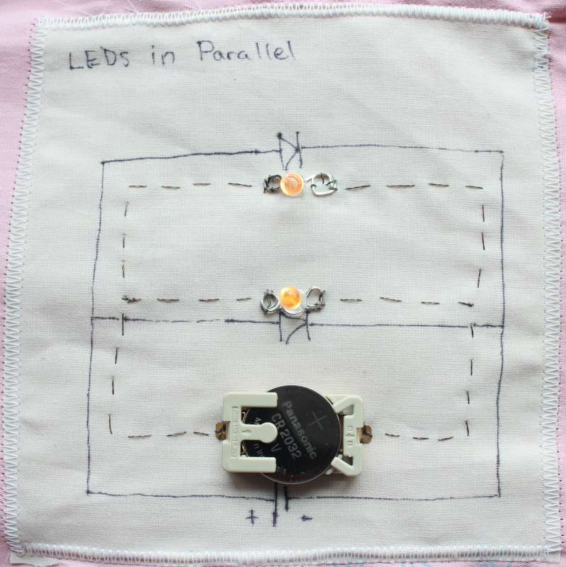
Sewing a soft circuit with a battery and a two LEDs involves nearly the same steps as a single LED circuit.
You begin by creating that loop containing the battery and one LED. Again, we don't need to worry about using a resistor because the conductive thread has some resistance and the coin cell battery cannot supply that much current.
Aside on battery cases: In the example on the right, I used a hard battery case instead of a soft one. Hard battery cases are easy to use and hold the battery snugly so there is no flickering - however they are bulky and less attractive. It's up to you what type to use!
Once you have the first loop done, simply add another LED by sewing from the positive leg of the second LED to the conductive trace leading to the positive leg of the first LED. Then sew the negative leg of the second LED to the conductive trace leading from the battery to the negative leg of the first LED.
The only trick here is to make sure your LEDs are oriented in the same direction!
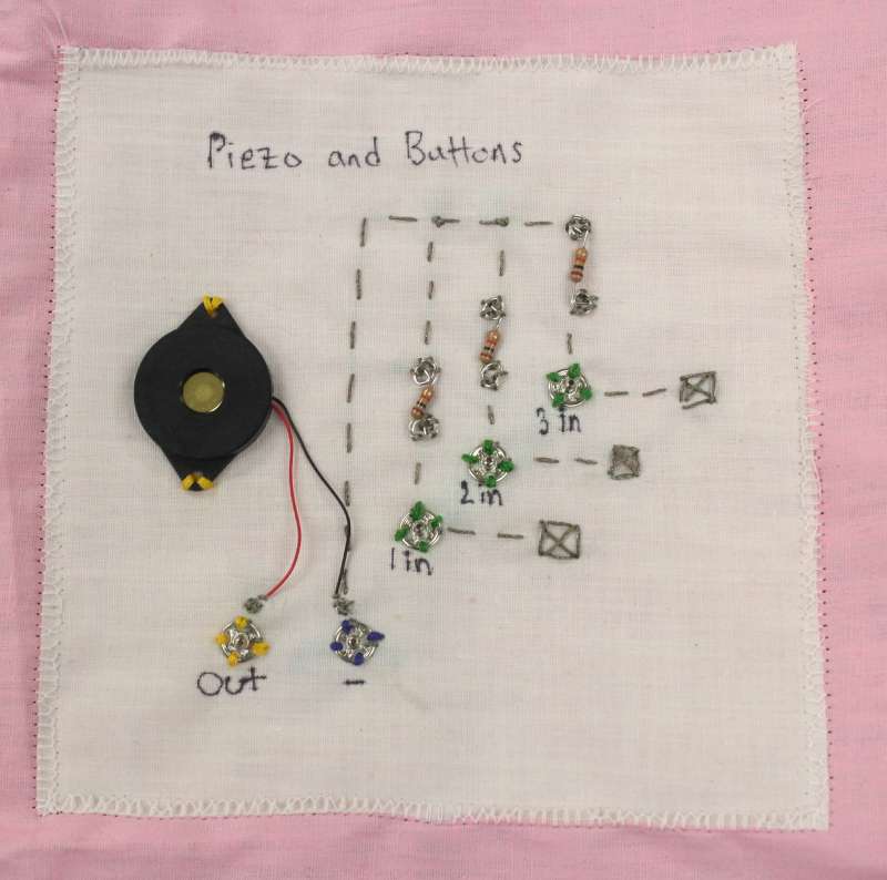
Tricolor LED with Photoresistors
Sewn Circuit with Tricolor LED and Three Photosensitive Resistors from katie dektar on Vimeo.
Creating a circuit with a color-changing tricolor LED is actually pretty simple. All you need is the tools for creating a simple LED circuit, as well as 3 photosensitive resistors, one tricolor LED, a 9V battery and a battery clip.
If you don't have these just laying around, you can buy the Tricolor LED Kit from my Etsy store!
Before we get started: if you aren't sure about the electronics behind this circuit, check out the electronics tutorial on it.
 Next, bend the leads of the components to make them easy to sew. I bent the legs of the three photosensitive resistors into little loops - the same on both sides - because they have no polarity. I bent the stranded wire from the ends of the battery clip into loops also because polarity is denoted by the wire color.
For my tricolor LED, the long leg is a common ground. I bent that one into a square to denote negative, and the other three I bent into circles at different heights so that I would be able to sew to them individually.
I then sewed my circuit together:
I connected the negative side of the battery to the common anode (square leg) with one piece of conductive thread.
With another piece of thread, I sewed from the positive side of the battery to one side of each of the 3 photosensitive resistors. After sewing one side of each resistor down, I cut and tied that piece of thread.
With a single piece of thread, I sewed from one of the remaining legs of the LED to the other side of one of the photosensitive resistors. I repeated this with the other two legs of the LED.

Because the resistance changes with light, I can change the color of the LED by covering up the resistors or by shining a light on them (see video below).
This is the same circuit that is inside my needlefelted sheep. The fun thing about soft electronics is that they can be shaped and molded into anything - no need to stick with a 2D surface like in this tutorial!
Multimeter Basics
A multimeter is a must-have for serious electronics, but one can get away without one for these basic circuits. Should you be looking to expand your horizons, consider grabbing one! Then you can check voltage, current, resistance and connectivity to help debug and test circuits (multi=many, meter=measure).
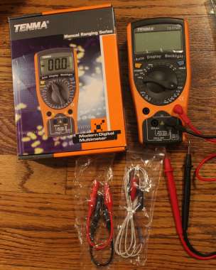
I got my multimeter from Newark.com, an electronics supply company. This one was $28, which is enough to get a good digital multimeter.
This multimeter came with the normal leads, but also alligator clips (useful) and temperature sensors (neat). It also came with a battery, which I appreciated.

Multimeters have several ports where you can plug in the leads. The black/ground always goes in COM, and the red/power moves around. You move the power to mA for measuring small currents, and to 20A max for large currents. If you don't do this right, it can blow the fuse in the multimeter!
Always check you have the red plugged into the correct port before turning on the multimeter and your circuit.
When measuring stuff, you have to turn the dial to tell the multimeter what you want to measure. For voltage and current you can choose between AC (alternating current, ~) and DC (direct current, —). Batteries supply direct current, while your wall supplies alternating.
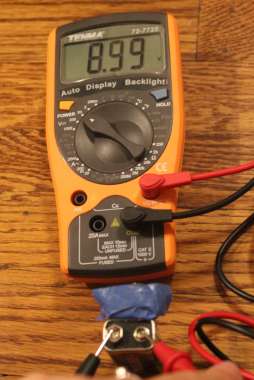
You always put the dial at a number that is greater than or equal to the value you expect. If I want to measure a 9 volt battery (left), I turn the dial to V, 20. If I set it to 2, I won't be able to see the voltage (off the charts!), while if I set it to 200, there won't be enough accuracy to tell me exactly the right number.
To measure voltage, you put the leads across the component (in parallel with the component). To the left I measure the voltage of a 9 volt battery -- at 8.99 volts it seems pretty charged!
To measure resistance, you again set the dial to greater than or equal to your expected value. If you don't know, guess and check! To the right I measure a resistor that is about 100 ohms.
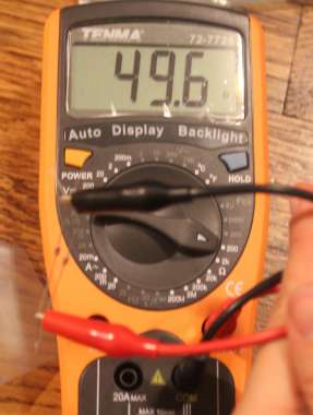
What happens to two resistors in parallel? The resistance halves! Two 100 ohm resistors in parallel are measured to the left.
You can remember this because it is like having two 'pipes' for the electrons to flow through -- more space for flowing is sort of like a bigger pipe.
Resistance is measured by the voltage drop from the red to black lead: V=IR all the way!
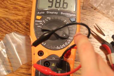
My favorite setting on a multimeter is the connectivity setting. You can touch the two leads to anything, and if the multimeter beeps than they are electrically connected with very low to no resistance. A wire, a piece of metal, a cup of salty water, a tongue -- all these things make the meter beep!
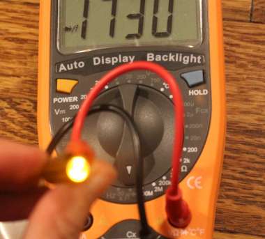
This connectivity setting is also the 'diode test' setting. Here I test an LED by hooking it up to the leads and switching the multimeter to diode test/connectivity. I'm not sure what the number displayed on the screen means, but then I haven't read the manual.
I believe connectivity is tested just by sending a little current through the leads.
Finally, measuring current! To measure current you must do two really important things so as not to break your multimeter.
1. Switch the red lead to the correct port -- 20mA or 20A depending on what you expect. If you don't know, play it safe by starting on the 20A setting.
2. Hook up the multimeter in series with the part of your circuit whose current you wish to measure. Series means that the electrons which flow through your circuit will also flow through the multimeter. There are no branches. If you do hook up the multimeter in parallel, the low resistance within the multimeter will allow all the current to flow through it, instantly blowing out the fuse!
After making sure you did 1 and 2, you may turn on the multimeter and read the current.
Arduino Basics
Interactive electronics can be far more fun and interesting than simple circuits, but creating a 'smart' circuit requires much more know-how. Unless, of course, you have a programmable microcontroller!
A microcontroller is like a small computer, able to store and execute a set of instructions via input/output pins. Programmable microcontrollers like the Arduino are great for hobbies and prototypes of electronics because they are easy to use. The Arduino is one of the most popular microcontrollers because it is inexpensive and open-source. There is a lot of documentation and many code samples available for Arduino.
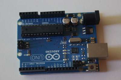
I use two Arduinos for my soft circuits. I start by prototyping my circuit using the Arduino Uno, which I got from Newark. The Uno is a great board - it has a power regulator built in, so you don't have to worry about connecting the power backwards. It also has a USB converter on-board allowing it to be immediately hooked up to a computer.
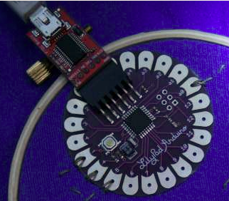
When I am done prototyping with the Uno, I transfer my code and circuit to the Lilypad Arduino, available on Sparkfun. This is a smaller, lighter Arduino on a board with holes through petals pins meant for sewing. However, the Lilypad does not have a power regulator so you have to be very careful not to break it by connecting power inappropriately, and also it requires a separate piece to connect to a computer via USB.
Programming the Arduino is relatively simple. To get everything hooked up and ready to go, download the Arduino software and follow the getting started guide.
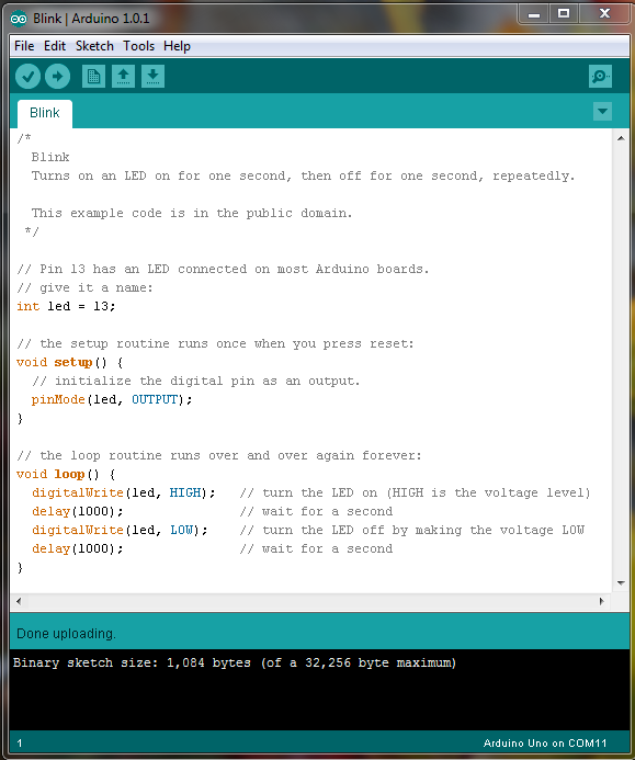
Once everything is hooked up, we will make the orange LED on the Arduino Uno blink. Hint: the final code is on the below; you can type it in yourself or load it from the Arduino sample libraries, File -> Examples -> 01.Basics -> Blink.
//setup is run once at the beginning:
void setup() {
}

// the loop routine runs over and over again forever:
void loop() {
}
First, every Arduino program must consist of two functions: setup() and loop(). The setup() function is run once at the beginning of execution; usually it will initialize variables and setup pins as input or output. The loop() function is run over and over again for the rest of the time. When the Arduino is reset or unplugged it will start from setup() again.
Because we want to blink the LED attached to pin 13, we will need to set pin 13 to be in 'output' mode. Arduino pins can be either input or output, meaning during a program you can either read the voltage at a pin or write a voltage to it (but not do both). To set the pin mode, set pinMode(13,OUTPUT);
A quick note on color
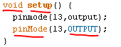
The Arduino GUI (graphical user interface) will automatically color reserved words orange, and static constants blue. This helps you tell if you typed something correctly, and also keeps you from using reserved keywords for other variables. To the left, pinmode (lowercase 'm') is not orange, while pinMode (uppercase 'M') is. This tells me that pinMode is the correct function.
Now for loop(). We want our LED to blink: one second on, then one second off, then repeat. The repeat is exactly what loop() will give us, so let's write code inside of loop() to do the turning on and turning off.
// the loop routine runs over and over again forever:
void loop() {
  digitalWrite(13,HIGH);
  digitalWrite(13,LOW);
}
To turn on a digital pin such as pin 13, you simply 'write' to that pin the value 'HIGH'. HIGH means the high voltage (i.e. 5V when connected to the computer, or 3V when connected to a 3V battery). Similarly, LOW means the ground voltage, 0V.
Unfortunately, the code above doesn't work. (Try uploading it to your Arduino with the -> button and see!) The reason? We don't wait between turning it on and turning it off.
// the loop routine runs over and over again forever:
void loop() {
  digitalWrite(13,HIGH);
  delay(1000);
  digitalWrite(13,LOW);
  delay(1000);
}
To add the delay between turning it on and turning it off, we use the function delay(ms). The argument to this is the number of milliseconds to wait. Since we want to have one second on and one second off, we will set delay(1000).
Put it all together and you get a blinking LED, controlled by the Arduino microcontroller and programmed by you yourself! Don't forget to test it with a LED: place the positive lead in pin 13 and the negative lead in ground and watch the blinkage.
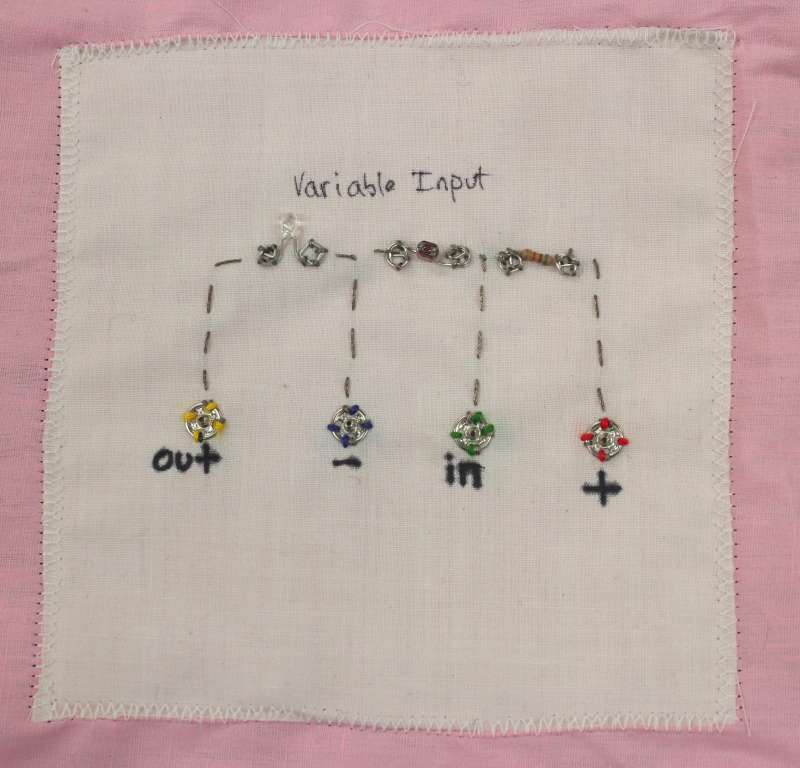
Variable Input: Arduino to Soft Circuit
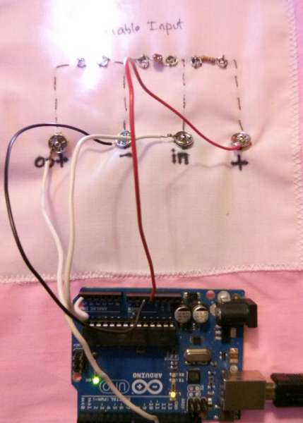
This simple Arduino project demonstrates how to get input and use it to do something -- in this case, change the brightness of an LED.
Our goal is to figure out the amount of light hitting the photosensitive resistor and use that to change the brightness of the LED. The circuit uses 3 components: one LED, one resistor, and one photosensitive resistor.
To control the LED, we can connect the negative end to ground, but connect the positive end to a Arduino pin that we can control. When we change the voltage of our 'out' pin, the brightness of the LED will also change.
We will use the two resistors to set up a 'voltage divider', in which the resistors are placed in series between ground and power, and we measure the voltage at their junction. We know that the total voltage drop across both resistors must be equal to the voltage of the power (in this case, if power is at +5 volts than the voltage drop across both must be 5 volts). We also know that the current through two elements in series is the same, but V=IR says that if their resistances are different we have different voltage drops across each.
Basically we get the equation V=IR for each resistor. Because I1 = I2, and V1 + V2 = 5, we can simplify this to V1 / R1 = (5 - V1) / R2 and thus see that R1 / R2 = V1 / (5 - V1). We see that the ratio of the resistances impacts the voltage drop across each resistor.
Ok, enough electronics; let's get coding.
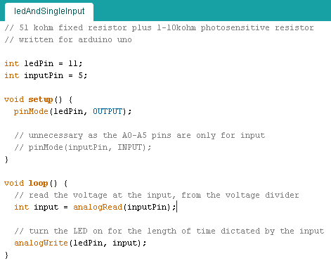
We will start by creating the 2 components of any Arduino project: the setup() and the loop() functions. Before going into these, we can also set variables to represent the pins that we want to use for input and output. In this case, I use pin 11 to control the LED, and the analog input pin 5 to read the voltage from my voltage divider.
In setup(), I let the Arduino know that pin 11 will be used for output. Because analog pin 5 is an input-only pin, I don't need to initialize it.
In the loop() function, we will read the voltage in from the inputPin, and write that exact voltage to the outputPin.
Upload it, and plug it all in, and there you have it! A simple Arduino circuit controlling the brightness of an LED with an Arduino!