Intro to Electronics for Soft Circuits
In the soft electronics tutorial, you can make an LED light up - but why? Knowing what is happening beyond the circuit diagram is not just interesting, but can greatly help with debugging and inventing your own circuits. This page is designed to give a brief overview to beginners, and is based off a class I teach at Stanford Splash, Workshop Weekend, and the Alaska Summer Research Academy.
Topics
- Electricity
- Current, Voltage and Resistance
- Components
- Circuits
- Current and Voltage Laws
- Simple Analysis
- Building a circuit: Tricolor LED + Photoresistors
Electricity
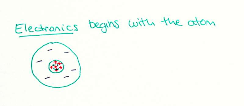
Electronics begins with the atom, the fundamental unit of matter.
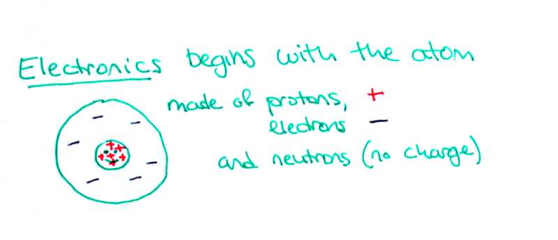
Atoms are made of protons, electrons and neutrons. Large protons have a positive charge, while small electrons have an equal but opposite negative charge.
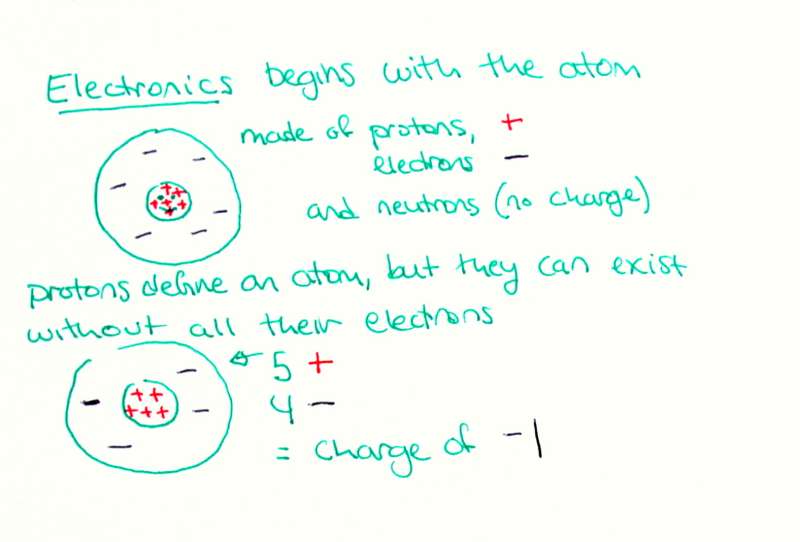
Although atoms are made of three distinct things, they are defined only by their number of protons. For example, a carbon atom must have six protons, but it can have as many neutrons or electrons as it wishes. Of course, it will not be very stable without four electrons - when the four positive charges from the protons are canceled out by the four negative ones from the electrons. Some atoms are better at being stable without all their electrons than others.
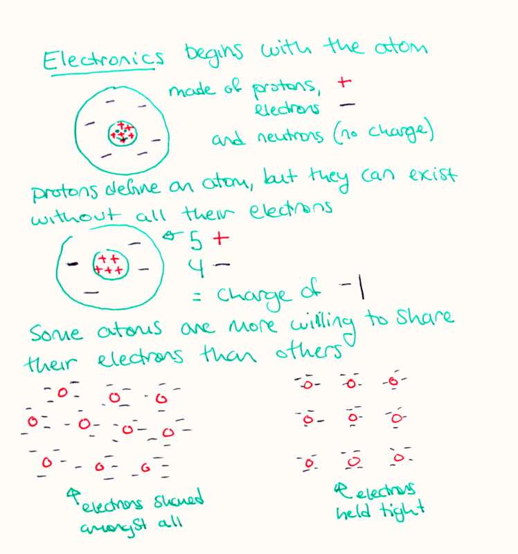
Materials are made from many atoms close together. When atoms are packed together into a material, they are able to interact - for example, they could repel, attract, bond, or share electrons. Some types of atoms are more willing to share their electrons with neighbors than others. In the diagram, you can see the material on the left has electrons dispersed among all the positive protons, while the diagram on the right shows protons that hold their electrons tightly and will not share with neighbors.
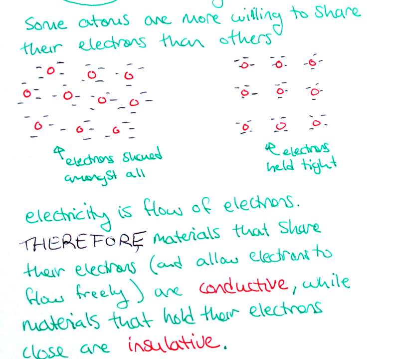
Electrons that are shared can "flow" between atoms in a material. Electricity is defined as the flow of electrons. We have learned that electricity flows through metals but not through plastics or fabrics. Therefore we can understand that metals share their electrons, while fabrics and plastics do not.
Materials that allow their electrons to flow are called conductors, while materials that restrict the flow of electrons are insulators.
Current, Voltage and Resistance
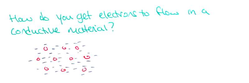
Electricity is the flow of electrons, but how do you get electrons to flow? They seem pretty happy where they are!
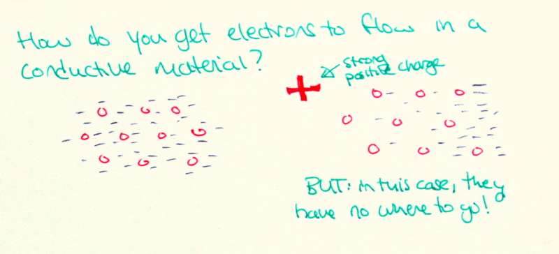
The answer is to use their charge against them. As we know from playing with magnets, opposites attract. Similarly with electronics: like charges repel while opposite charges attract. If we bring a really big negative charge near the electrons, they will be repelled by it and flee to a far end of the material.
note: the diagram to the left is incorrect - that should be a strong negative charge, since it repels the electrons!
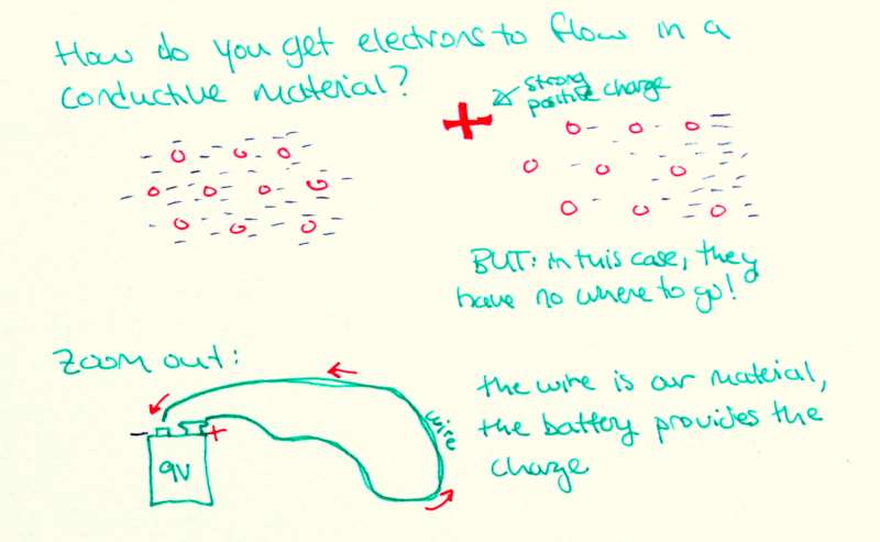
Let's zoom out, and use a 9V ("nine volt") battery as our source of charge, and a wire as our conductive material. Think of the battery as something with a whole lot of extra electrons at the negative end, and not enough electrons at the positive end. If we attach it to the initially uncharged wire, the electrons will flow from the negative end, through the wire, to the positive end.
This is possible because the metal atoms in the wire are willing to share their electrons.
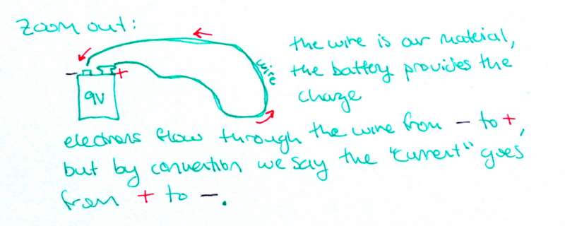
Maybe you noticed that I drew the little red arrows moving from the positive (+) side of the 9V to the negative (-) side. This was not a mistake - convention says the current flows from positive to negative. This convention was established before people knew that the negative electrons were what actually moved! Even though we all know the electrons are what is moving, we stick with convention and say current goes in the opposite direction.
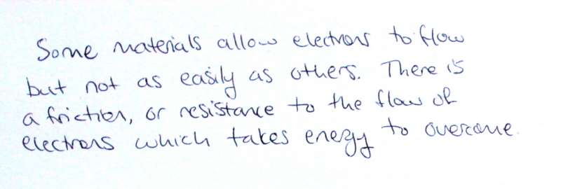 Actually, connecting a conductor between the terminals of a battery short circuits the battery - all the electrons whiz through the wire super quickly and the battery & wire both get very hot - I don't recommend it. Not all conductive materials are as easy for electrons to pass through as a wire. Some materials have more internal friction, or resistance to the flow of electrons, and it takes energy to overcome this resistance.
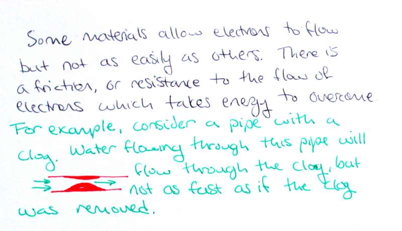 Take, for example, a clogged pipe (or artery!) Water can flow through the pipe, but not as quickly as if the clog was not there.
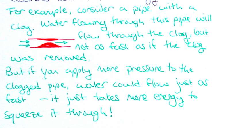 If you apply more pressure to the water, it could potentially flow just as fast as when the pipe is unclogged. It just takes more energy to get the same rate of flow. (That's why people with high cholesterol & clogged arteries have heart trouble - their hearts have to work extra hard to pump blood at the same rate!)
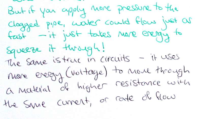 Just as pipes can have resistance which restricts the flow of water, so can electrical components have resistance which restricts the flow of electrons. Materials of higher resistance require more energy to pass the same rate of flow.
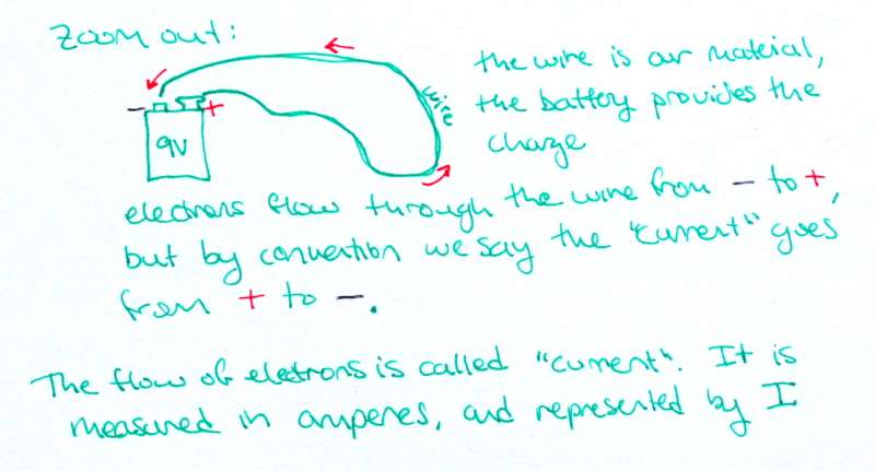
The flow of electrons is called current. Current is measured in the unit amperes and represented by the letter I.
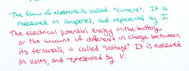
The electrical potential energy of the battery - the amount of difference in charge between its terminals, is called voltage. It is measured in the unit volts, and represented by the letter V.
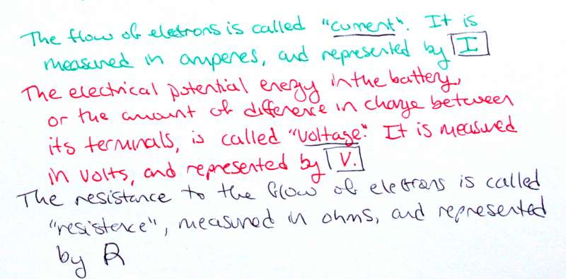
The resistance to the flow of electrons is called resistance and measured in the unit ohms (Ω). It is represented by the letter R.
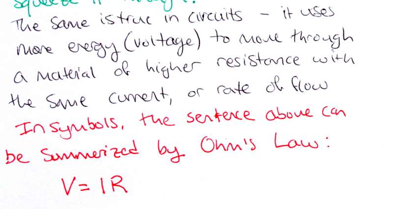
Thinking about the pipe example for current (water flow), voltage (water pressure), and resistance (clogs), we can see they are all related. Higher voltage means higher current; higher resistance means lower current, and higher voltage also leads to higher resistance. We can summarize these relationships in electronics using a fundamental law, Ohm's Law:
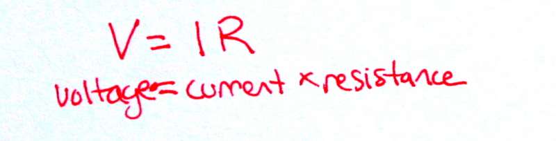
V = I x R
voltage = current x resistance
Components
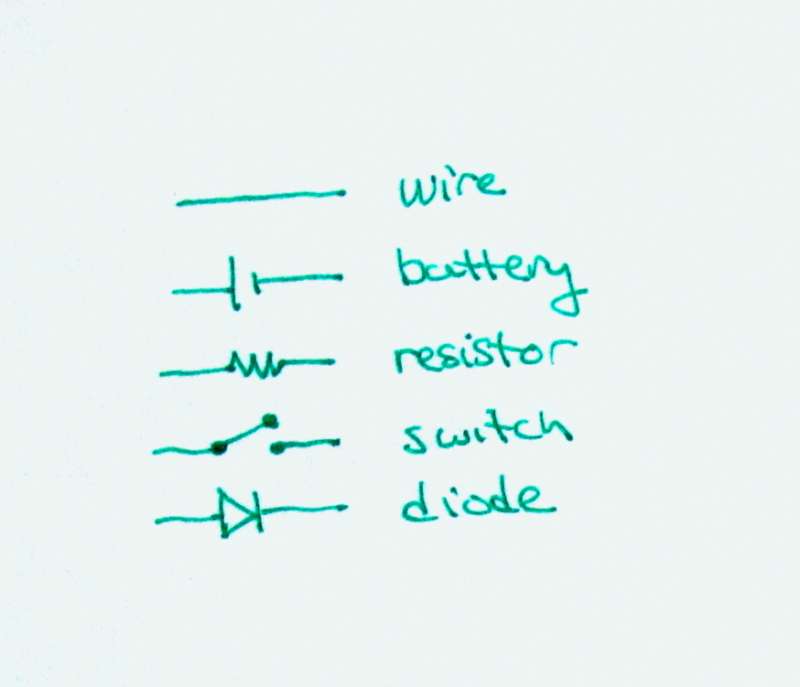
There are only about 7 different types of basic electrical components. In the following sections, I will use the symbols to the right to represent wire, batteries, resistors, switches and diodes: the most common components in these tutorials.
Wire and switches are the most similar in life to their drawings. A wire is any plain line.
A switch is shown as a break in a wire.
While we all know what a switch looks like, some of the other components used in electric circuits may be a little unfamiliar. Let's look at some components more closely:
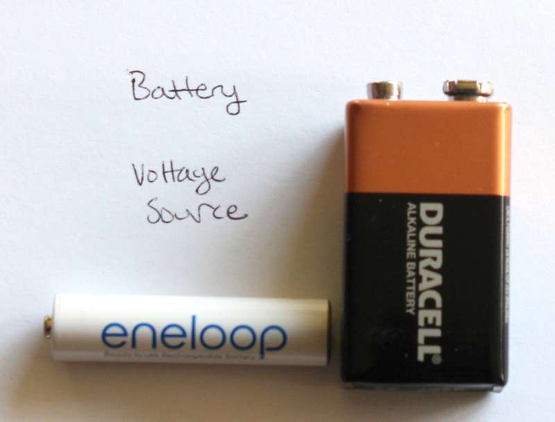
A battery is represented as a long line (positive terminal) and a short line (negative terminal) separated by a space showing that electrons don't move directly from + to -.
Batteries come in all shapes and sizes, and a range of voltages. The big square battery to the left is a 9 volt. The rechargeable AAA battery is about 1.5 volts. Coin cell batteries are often 3 volts.
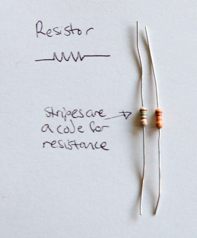
A resistor is represented by a zig-zag which looks a little like a filament of a incandescent light bulb (a kind of resistor which gets so hot that it glows!)
Many resistors look similar, but they can have vastly different resistances. You can find out the resistance using a chart to interpret the colors of their stripes.
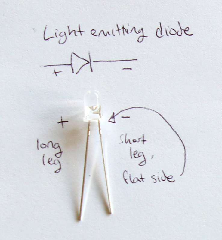
A diode, like an LED, is shown as an arrow with a line, showing that current can flow only in one direction through the component.
Diodes, including LEDs, have a polarity - they only work when the current flows through them in one direction. Often, LEDs have physical features to help us determine their polarity, including: a long leg (+ side), a larger terminal (also + side), or a flat bit on the outer plastic ridge (- side).
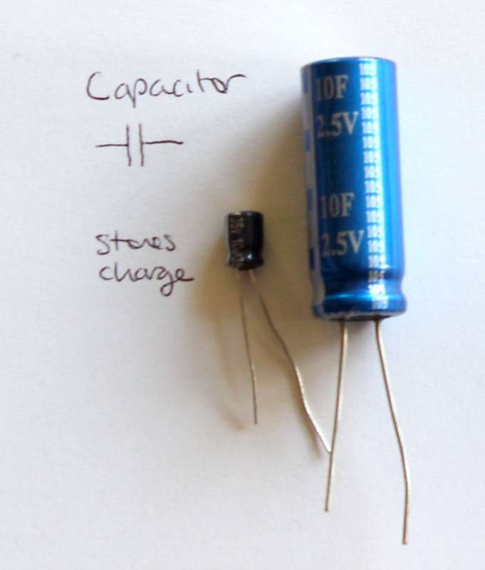
Capacitors are similar to batteries in that they can store a charge (energy). Unlike batteries, they can be charged and discharged quickly. They are useful as you get into more complex circuits, but I don't plan to cover them in this tutorial.
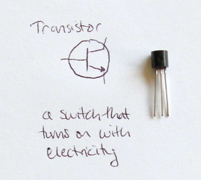
Transistors are another type of component. I don't plan to cover them in this tutorial, but they are pretty cool: they can be thought of as a switch that is turned on using electricity. Transistors are the basic component in computers.
Circuits
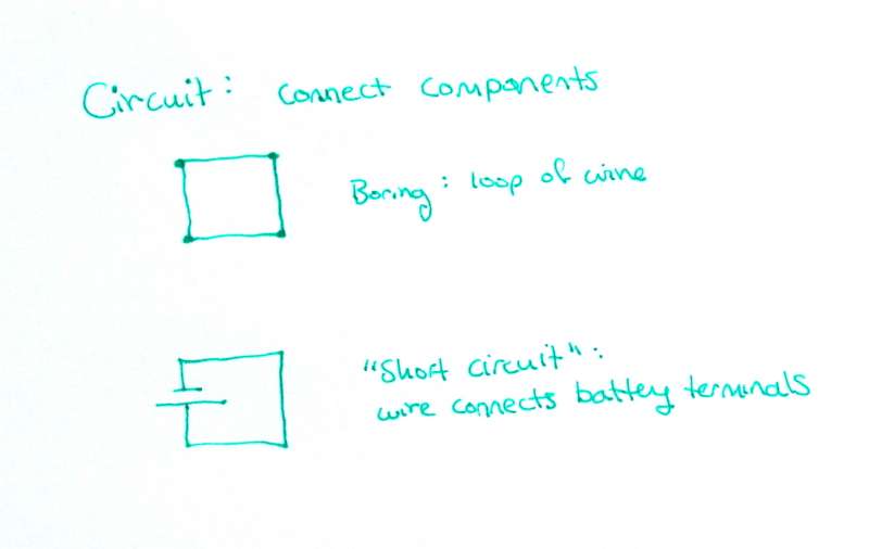
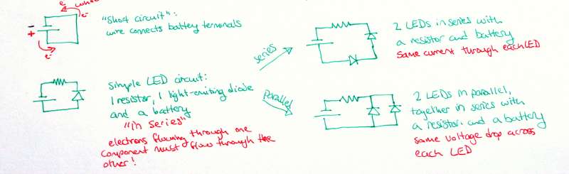
The definition of circuit is a roughly circular path, that begins and ends in the same place. In electronics, a circuit is connected electronic components through which electricity can flow. Recall that electricity will only flow if there is a closed path, hence the word 'circuit'. The most basic circuit is simply a loop of wire - but this is rather boring. A closed loop of wire will remain static because there is no source of energy (voltage).
A more interesting circuit is a battery with a wire connecting its terminals. This circuit's source of energy is the electrical potential energy in the battery.
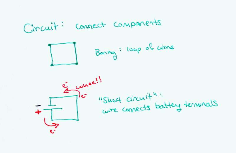
As soon as the battery is connected to the wire, all the electrons will immediately zoom from the negative pole to the positive pole (recall: the convention says current flows from + to -, but the electrons actually go from - to +).
Connecting a battery to a wire like this is called short circuiting the battery. In real life, the battery would get very hot, and quickly lose all of its electrical potential energy. It would then be useless as a battery.
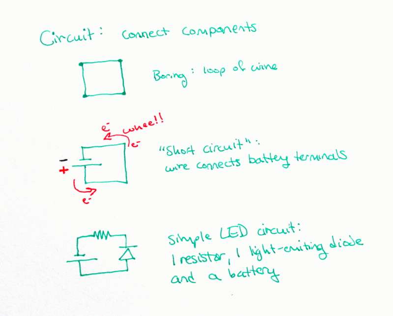
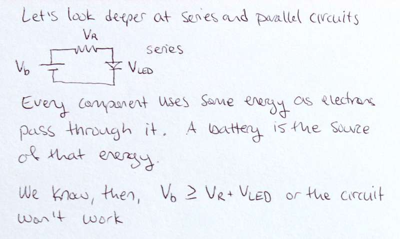
Let's add some more components. A resistor will keep the current from zooming through the wire and shorting the battery. A light-emitting diode will light up when correct amount of current flows through it.
Let's look at this new circuit a little closer. Imagine you are an electron - as you flow through the circuit, you must move through every component sequentially. You can't, for example, jump straight from the battery to the resistor without going through the diode, since there is no electrical path between the two that doesn't include the diode.
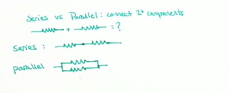
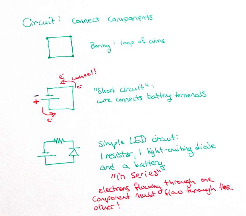
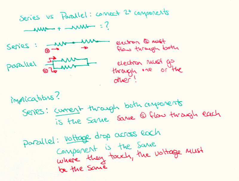
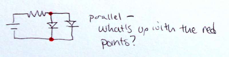
When components are in line with each other like beads on a string, they are in series.Two components can also be connected in parallel: this is when there are two possible electrical paths, each through a different component. Series and parallel may seem similar, but they actually have quite different electrical properties.
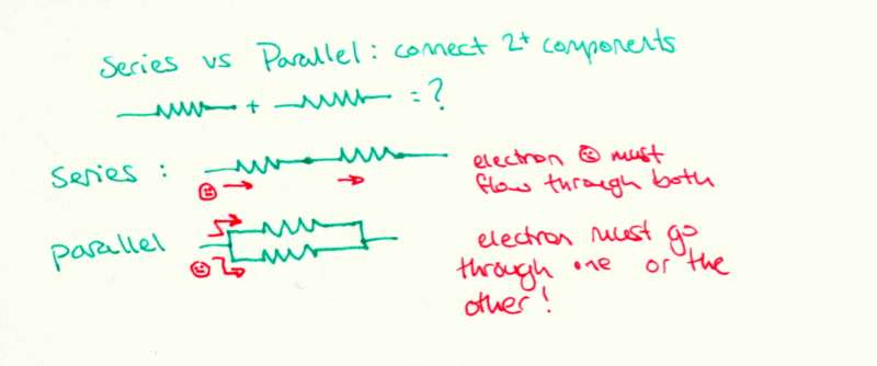
For two components in series, an electron that goes through the first component must go through the second. Similarly, the current though the first component must be the the same as the current through the second (note: current is really just electrons per unit time).
For two components in parallel, an electron cannot go through both components. It must go through one or the other only. Therefore, the current need not be the same through each component. But the voltage drop across each component must be the same. Voltage drop is a decrease in potential energy - and the potential energy before the components compared to after them is the same regardless of path. That's sort of the same as saying it takes that the potential energy of a ball changes the same amount when it is moved from 5 feet in the air to the ground, no matter if it was dropped or rolled down a ramp.
Let's use the concepts of series and parallel circuits to make circuits with 2 LEDs. The first will have the 2 LEDs in series, and the second will have the 2 LEDs in parallel.
In the first circuit, we know we have the same current flowing through each LED, because they are in series.
In the second circuit, we know the voltage drop across each LED is the same, because they are in parallel.
Current and Voltage Laws
We discussed series and parallel circuits in broad terms, but now let's look at them more closely.
First, we have to understand that every component uses some energy as electrons pass through it. Things like motors and incandescent lights and toasters use significantly more energy than highly efficient LEDs, but everything still uses some.
That energy comes from the battery's store of electrical potential energy. Voltage is a measure of electrical potential energy, so we can also say that across any component there is some drop in voltage. If the battery can power the circuit, the voltage of the battery must be at least more than the sum of the voltage drops across all the components in that circuit.
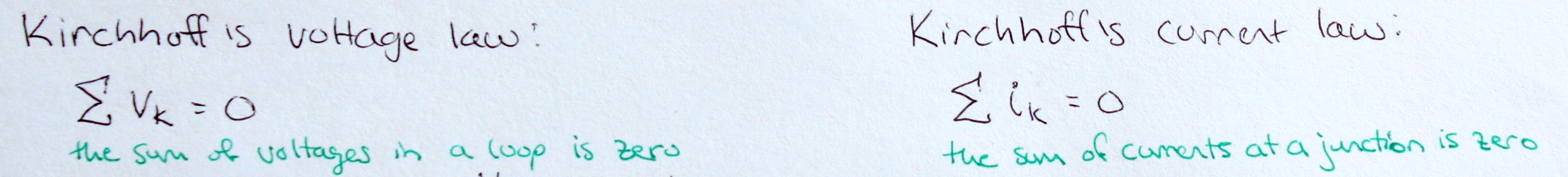
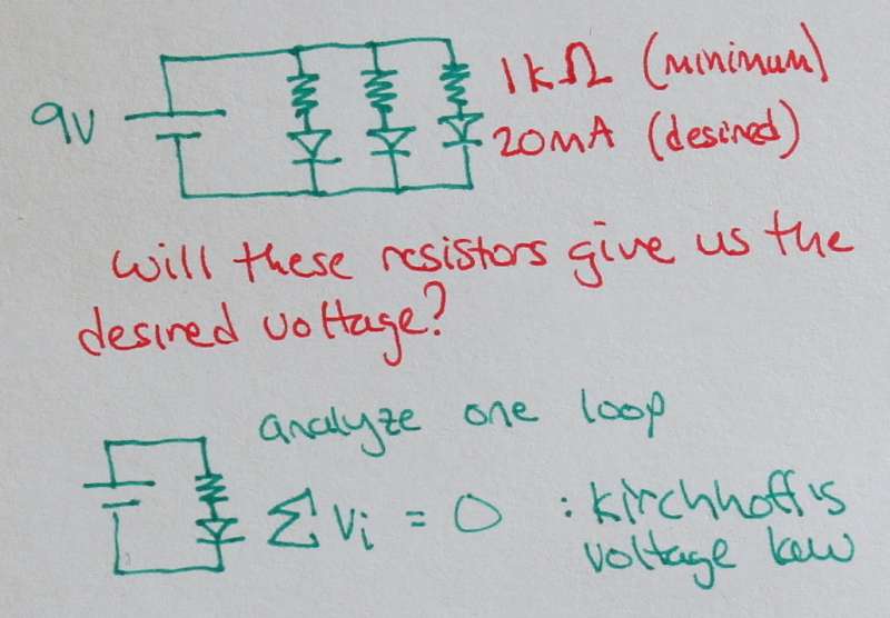
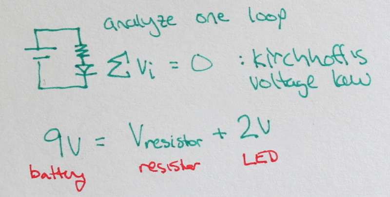
In fact, the voltage of the battery is exactly equal to the sum of the voltage drops across each component. This is known as Kirchhoff's Voltage Law, and is a fundamental law of electronics.
Kirchhoff's voltage law: the sum of voltages in a loop is zero.
Thinking about the series circuit gave us the voltage law. What about parallel circuits? Well, the most interesting part of parallel circuits is the junction where one wire splits into many.
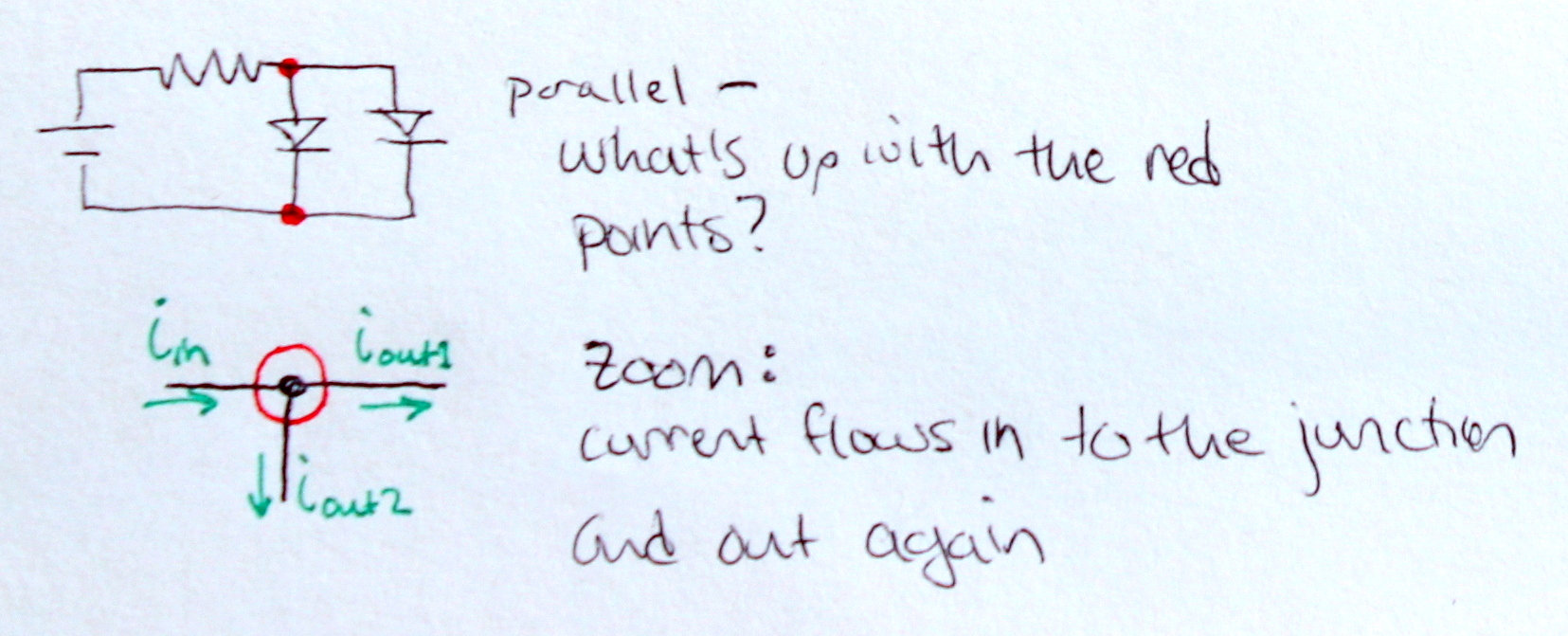
Zooming in, we can think about the current at an intersection. Some current flows in to the intersection, and some flows out through each branch.
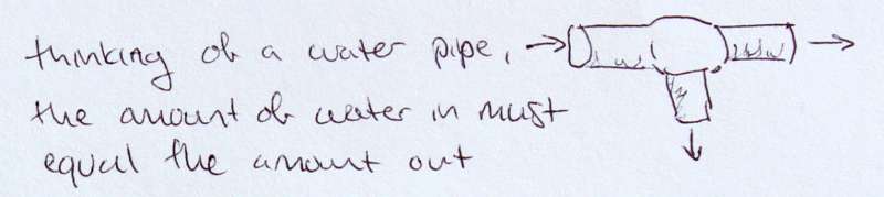
Let's go back to the water analogy, and think of the junction as a pipe. Water flows in one branch, and out the other two. In this case, we can see that the amount of water entering the first branch must be equal to the sum of the amounts leaving the others. Conservation of mass. If the water out wasn't equal to the water in, there would be a black hole in the middle of the junction!
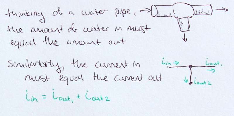
Current is the flow of electrons, so in a way it is very similar to the flow of water. Applying the logic from the water pipes to the circuit, we can see that the current in must be equal to the sum of the currents out.
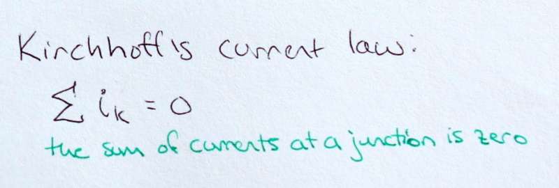
If we consider the currents in as 'positive' current, and the current out as 'negative' current, we see that the sum of a currents at a junction is zero. This is known as Kirchhoff's current law, and is the third fundamental law of electronics.
Laying down the Laws: Circuit Analysis
Recall, our three laws of electronics:
Ohm's law: V=IR
Kirchhoff's Voltage law: The sum of the voltages in a loop zero
Kirchhoff's Current law: The sum of the currents at a junction is zero
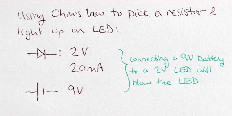
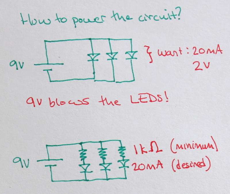
Ok, let's use these laws to pick a resistor for a battery and LED to make a circuit that doesn't blow the LED but still lights it up brightly. This is common in electronics - you have knowledge about some components, and need to figure out what others to use to make everything work together correctly. What do we know? The specs:
The battery is a 9V,
The LED uses 2V and 20mA to run optimally. More current could blow it.
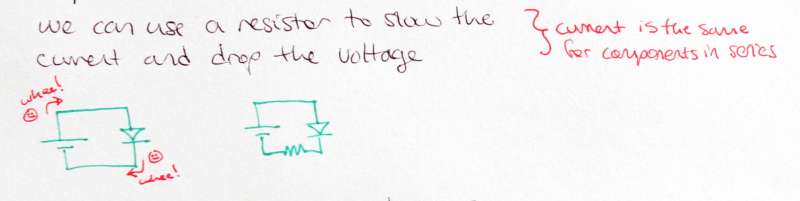
It makes sense to use a resistor to slow the current and drop the voltage. The resistance from the resistor will keep the electrons from blowing through the LED at a huge current, and blowing it out.
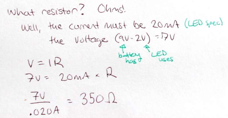
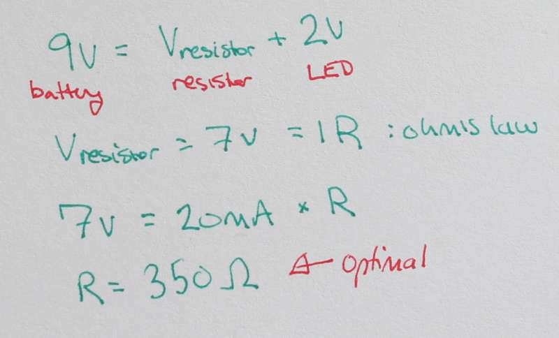
It takes a little math to figure out what resistor to use. First, we will use the voltage law to figure out what the voltage drop across the resistor should be. We know the sum of the voltages in the circuit is zero; the battery has +9V, and the LED takes -2V. That leaves us with 7V for the resistor.
Second, we plug this in to Ohm's law, V=IR. We know that V = 7V, and we want I = 20mA (recall: the current is the same for every component in series, so if we want 20mA through the LED we need 20mA through the resistors.). R = 7V / 20mA = 350 Ω.
Ta da! The fundamental laws let us make a nice circuit!
Building a Circuit: Tricolor LED and Photosensitive Resistors
Static LEDs are all very well, but circuits are way more fun when they are interactive. But can you build an interactive circuit with only the knowledge about Kirchhoff's laws, Ohm's law and the other basic electronics we've covered so far? Yes!
Let's make a circuit with a tricolor LED (an LED that is really like a red, green and blue LED all in one package). Later we can sew this circuit as a proof of concept.
Tricolor LEDs are super cool - like the pixels on your computer, they can be made to display any color in the rainbow by combining the right amounts of red, green and blue. (For more on color mixing, check out this color mixing app I wrote for a digital photography class at Stanford!)
We can use photosensitive resistors - resistors which change their resistance with changes in light - as our input. Since all resistors limit current, and more resistance means less current (V=IR), we can understand that as the resistance in these guys changes, the current running through them will change. Hook up one of the photosensitive resistors to an LED, and you will control the brightness of that LED with the ambient light against the photoresistor.
If we use one photoresistor for each of the three colors of the tricolor LED, we can change the amount of red, green and blue it produces by changing the amount of ambient light hitting the respective photoresistors.
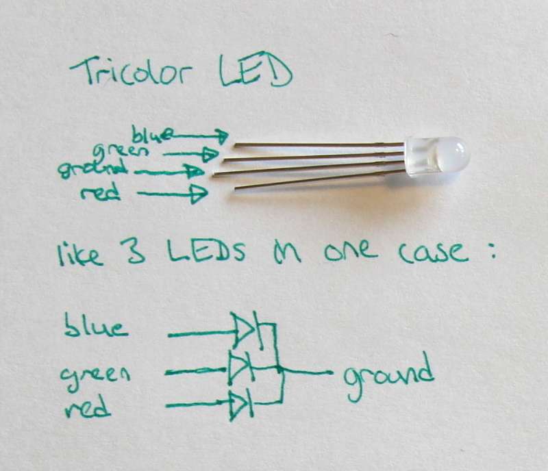
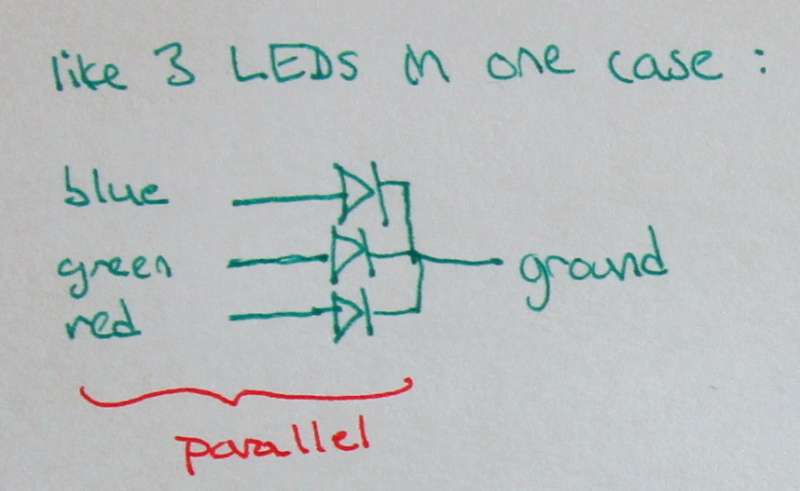
Let's look more carefully at our components. This tricolor LED has 4 legs: three positive legs for red, green and blue, and one negative leg which is a common ground. We can imagine the LED to be exactly the same as 3 differently colored LEDs all in parallel, as shown in the diagram to the left.
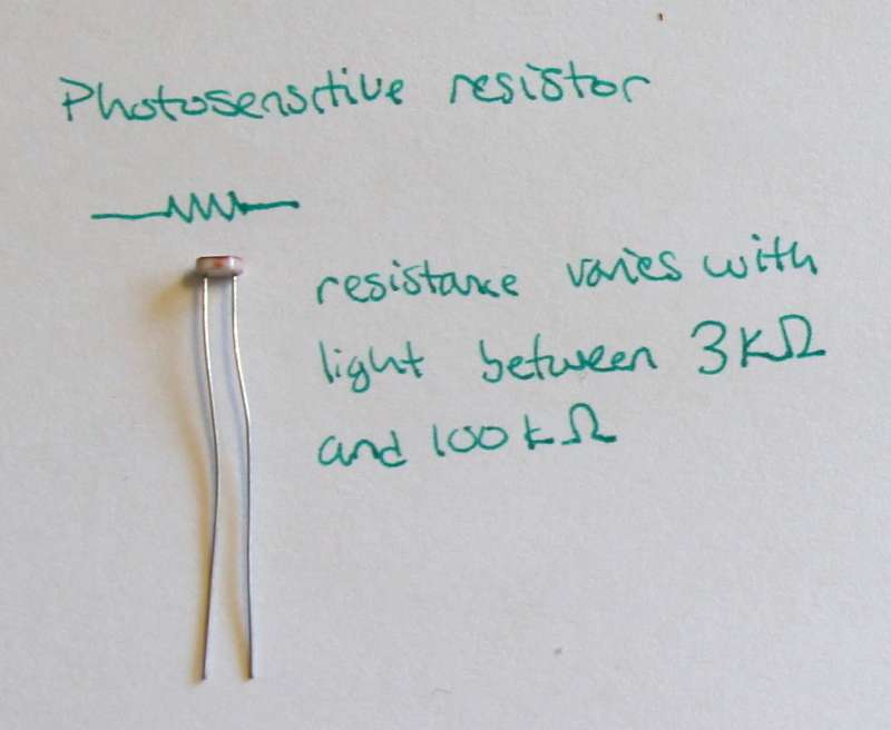
The photosensitive resistor is just like any other resistor - it has two, unpolar legs. However, the resistance of this guy varies between 1kΩ and 100kΩ. For this particular photoresistor, more light means less resistance.
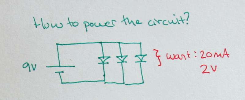
Now let's make the circuit. The tricolor LED's blue component required 3.2V of voltage, so we need to use a 9V battery for power (a 3V battery may not supply enough voltage to turn on the blue LED). The other components require about 2V of voltage. All the parts of the LED operate well at 20mA of current.
Kirchhoff's voltage law shows that in a loop, voltages sum to zero. Looking at the inner loop of this circuit, we can see that the 9V drop across the battery must be equal to a 9V drop across one of the LEDs. But the LED only takes 2V - so this would certainly blow it!
Our solution then is to add photoresistors to the circuit. We add one in series with each of the LEDs, to allow them to be individually controlled.
Thinking about this system, we know the resistance of our photoresistors ranges from 1kΩ to 100kΩ, and we know the LEDs want about 20mA of current. Is it going to work? Type to pull out the laws of electronics and see!
Let's analyze one loop again with Kirchhoff's voltage law.
The voltage drop across the photoresistor plus the voltage drop across the LED is equal to the voltage of the battery.
So the voltage drop across the photoresistor is 7V.
Now, apply Ohm's law: V=IR, to find the optimal resistance for some resistor in this circuit. We know I = 20mA because the current for elements in series is constant, and we know V = 7 for the resistor. Solving for R gives R = 350Ω. That means a resistor could be as low as 350Ω and still the LED wouldn't burn out in this circuit.
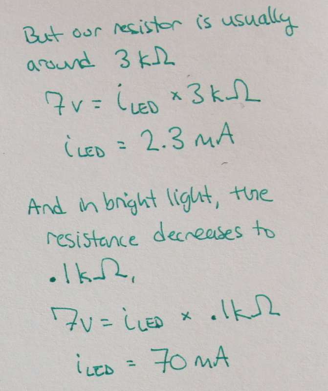
Our photoresistor is actually around 3kΩ, which means we don't have to worry about burning the out the LED. But will it still light up? Using Ohm's law, we can find the current through the photoresistor if the resistance is 3kΩ and the voltage drop is 7V. Looks like the current would be 2.3mA, which is still enough to turn on the LED.
When our photoresistor is in really bright light, the resistance decreases even to 10Ω. In this case, the current through the photoresistor and LED would be 70mA based on Ohm's law. That's pretty high, but the LED should still be fine.
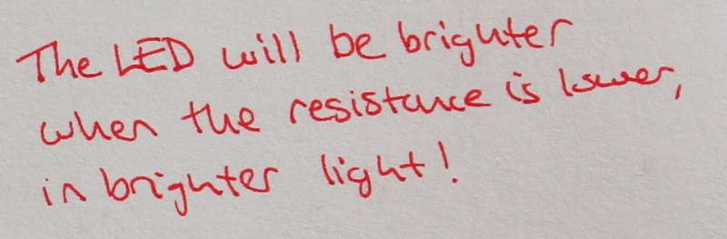
Since the photoresistor's resistance decreases with brighter light, we can tell that the tricolor LED will be brighter when the light hitting the photoresistors is brighter.
Ok, that was educational - but what does this circuit actually look like, and how can we make it? You can buy the soft circuit components with the Tricolor LED kit from my Etsy store. Then check out the sewing circuits tutorial on sewing this circuit.